
R1 Spec Ford Fiesta
Effectively the R1 spec Ford Fiesta is an entry level into the Word Rally Championship (WRC). The class was developed by Ford and M-Sport based on the production model car. Many of us are probably familiar with the Fiesta World Rally Car or Ken Block’s Gymkhana machines. Ford wanted to include a pathway from entry level to pinnacle. They used this ideology in the 70’s with the Escort.
Car History
This little rally car started life as an Australian delivered Fiesta Zetec S road car. After a short time on the public roads it was turned into a rally car using an M-Sport R1 kit. Along with the weld in roll cage, seats and suspension, several other options arrived in the crate. These included braided brake and fuel lines, a rally wiring loom, a roof vent, lightweight door trims and upgraded brake linings. It was the first Australian Fiesta to be built locally from an M-Sport kit.
The R1 specs are very strict to keep competition fair and costs down. This means that the cars are almost completely production based similar to Group N. This spec does have its advantages and it has its drawbacks too. Having a standard front differential means plenty of wheel spin out of corners. The brakes too are adequate, however not brilliant.
Upgrades needed
After two rallies in our stables at the end of 2016, the current owner requested some upgrades. Grabbing the handbrake when needed was tricky due to the factory position of the lever. Also the cable to the rear drum brakes could easily be stretched. The rear drums were not very inspiring either.
To upgrade the braking system meant departing from R1. The CAMS rules allow us the modifications no problems. It would simply mean the car would no longer be eligible to enter WRC events. The owner was not concerned about the WRC and so the decision was made to fit a hydraulic handbrake (vertical position) and disc brake rear end. A LSD would also go into the gearbox at the same time.
Making Space
We needed some room to position the hydraulic handbrake unit on the tunnel. Already jostling for space was the factory handbrake, M-sport switch panel and brake bias valve. Relocating the switch panel and wiring was the biggest challenge. The plastic shrouds around the gear stick were removed and the switch panel unbolted for a look.
We soon found the wiring loom was pre-fabricated to the exact length. A new panel of 1.5mm aluminium was fabricated to fit in the void of the centre console above the gear stick. The switches were relocated to the new panel and a couple of wires had to be cut and lengthened. We managed to gain some slack in the loom by cutting cable ties and re-routing some of the wiring.
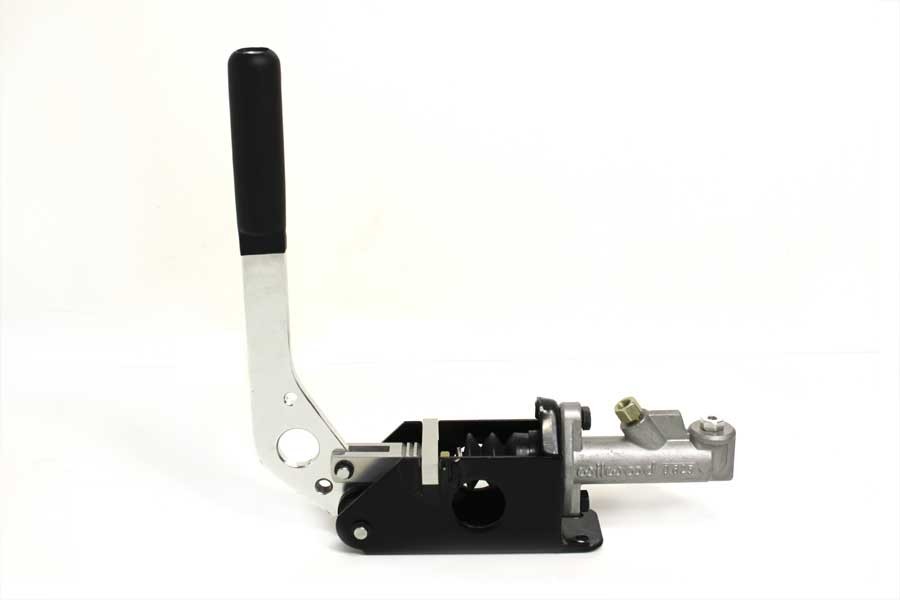
Hydraulic Handbrake
Next the handbrake lever and cable was removed from the tunnel. This work coincided with the removal of the drum brakes on the rear beam axle. Using two of the threads on the tunnel, we found the hydraulic handbrake could be set in a suitable position. Two new mounting holes were marked in the tunnel, drilled and tapped. Two new bolts were wound in from underneath the car so the threads protruded through. Four nylocks and washers were then used to bolt the handbrake unit securely into position.
Brake lines
The M-sport bias valve was then bolted back into position. Having in board brake lines saved some time and money. We had to make up new lines from the bias valve to the handbrake and handbrake to the tee at the rear of the car. The tee and bias valve required straight fittings to match up, we used banjo fittings on the handbrake. In between, dash 3 stainless steel braided line was used. Hard line and a flaring tool can be used too and does work quite well. The parts may be cheaper, however it takes longer to make it all up. Also care needs to be taken to form smooth bends and not kink the pipes.
With the lines cut to the correct length and the fittings all on loose, everything was carefully tightened. We used a rubber lined P clip to hold one of the lines in place. The rest of the lines were cable tied onto existing clips fixed to the body. All the lines throughout the car were double and triple checked to make sure they were tight.
Final Steps
Before the final stage, the handbrake lever was adjusted to the correct position and locked in place. All of the other bolts and retaining clips were tightened around the handbrake and checked for binding.
The brakes were then bled without problems. We have learned through experience that it is wise to check all fittings during bleeding. A tiny weep can soon lead to a puddle or air leakage in the system. If picked up early, a “nip up” is often all that is required to seal a fitting.
The next post will cover fitting the rear disc brakes.


